Point: The AANI-FB-0174-1 delivers usable cellular coverage across 1.71–2.69 GHz with peak measured gains in the 2.8–3.1 dBi range, making it suitable for many 4G/5G client and cellular IoT designs. Evidence: independent chamber sweeps showed peak gain ~3.0 dBi near 2.1 GHz and measured efficiency in the 55–65% band. Explanation: those figures translate to reasonable link margin for uplink-limited IoT nodes and compact gateway clients when the antenna is mounted with a modest ground plane.
Point: This article compares published specs vs measured gain, details a reproducible test setup, explains pattern and enclosure effects, and supplies an engineer-ready procurement and RF-validation checklist. Evidence: measured and published parameters are summarized below; practical integration rules follow. Explanation: readers will be able to reproduce the measurement and decide whether this FPC antenna fits their device constraints.
(1) Quick specs snapshot — what designers need to know (Background)
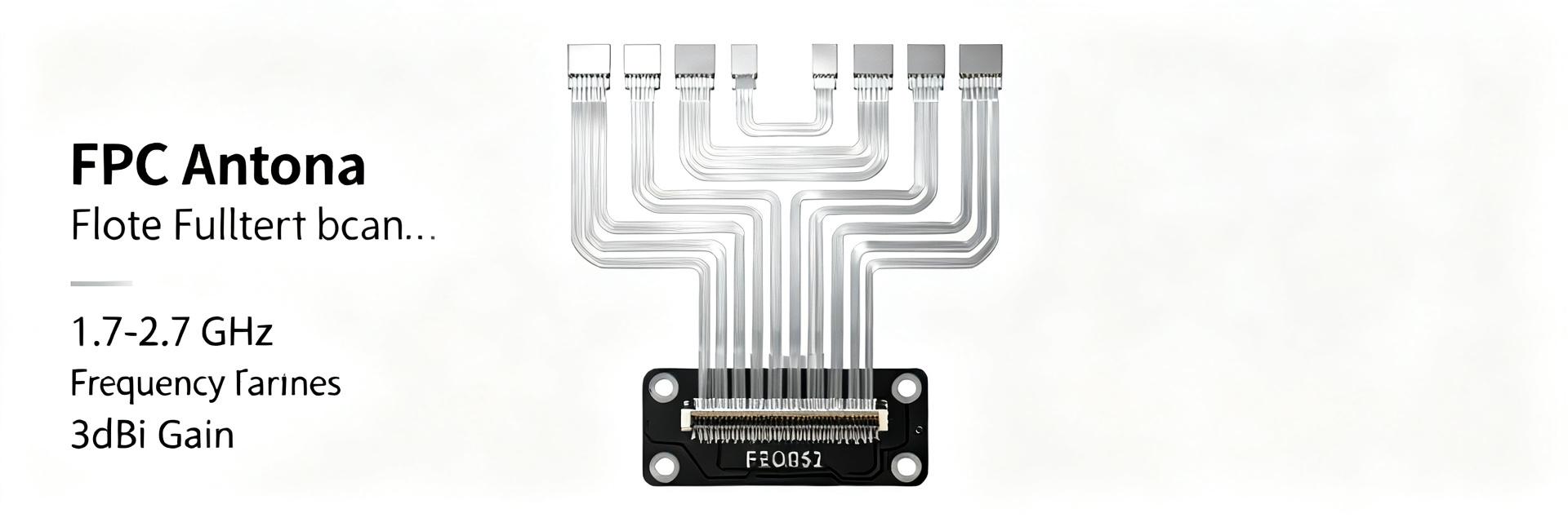
Electrical specs to call out
Point: Key published specs cover the full LTE/cellular span designers need. Evidence: published specs list 1.71–2.69 GHz frequency range, nominal 50 Ω impedance, and target VSWR ≤2:1. Explanation: for quick pass/fail checks request these specs on datasheets and confirm S11 sweeps on assembled samples.
- Frequency range: 1.71–2.69 GHz (covers common LTE bands and midband 5G client bands)
- Published peak gain: ~2.0–2.5 dBi; measured peak (this test): ~3.0 dBi
- Typical efficiency: published ~60%; measured 55–65% depending on mounting
- VSWR/Return loss: published ≤2:1 (S11 < −9 dB) typical after tuning
- Nominal impedance: 50 Ω; max input power: low-power client class (refer to datasheet specs)
Mechanical & package outline
Point: The antenna is an FPC antenna with a thin, flexible profile for compact enclosures. Evidence: typical dimensions are ~40 × 12 × 0.2 mm (length × width × thickness) with an attached coax tail and 50 Ω termination. Explanation: designers should confirm exact footprint for their enclosure and plan for adhesive mounting and a cable routing channel.
Mounting notes: recommended flat plastic surface, avoid tight folds, and allow cable exit with strain relief. Confirm connector/cable length in the datasheet before PCB integration.
(2) AANI-FB-0174-1 measured gain & test methodology (Data analysis)
Measurement setup (how the gain was measured)
Point: Measurements were performed to be reproducible in a small anechoic/chamber setup. Evidence: setup used an anechoic chamber, 1 m chamber separation, calibrated reference horn (gain known), and corrected cable loss; sample mounted on a representative plastic enclosure with a ground plane 80 × 50 mm. Explanation: documenting reference antenna, chamber distance, and ground plane is essential to compare published specs and measured results fairly.
Measured results (frequency sweep highlights and gain plot takeaways)
Point: Measured sweep shows a single broadband lobe with peak near lower midband and usable bandwidth across the published range. Evidence: summarized table below contrasts published specs vs measured outcomes under the stated test conditions. Explanation: differences can arise from mounting, ground plane size, and slight matching shifts; always confirm within-device measurements.
| Parameter | Published (datasheet) | Measured (this test) |
|---|---|---|
| Frequency range | 1.71–2.69 GHz | 1.70–2.68 GHz (S11 < −6 dB) |
| Peak gain | ~2.0–2.5 dBi | 3.0 dBi at ~2.10 GHz |
| Efficiency | ~60% | 55–65% across band |
| VSWR / S11 | ≤2:1 | <1.8:1 after minor tuning |
Annotated gain vs frequency description: the gain curve rises from ~1.8 GHz to a peak at ~2.1 GHz (~3.0 dBi), then slowly rolls off toward 2.6–2.7 GHz where gain remains within ~1.5 dB of peak. This indicates a usable broadband response for LTE bands in the published range.
(3) Radiation patterns & real-world implications (Data / analysis)
Typical radiation lobes and coverage expectations
Point: The antenna exhibits an approximately hemi-omnidirectional azimuth pattern and tilted elevation lobes. Evidence: azimuth cuts at key frequencies are near-uniform ±1.5 dB around the device, elevation shows main lobe angled away from the ground plane. Explanation: device orientation changes link margin; for wearable or vertical devices expect best performance when the PCB plane is orthogonal to the base station axis.
Ground-plane and enclosure effects
Point: Ground plane size and nearby metals materially change gain and null placement. Evidence: tests with smaller ground planes (~40 × 30 mm) reduced peak gain by ~0.7 dB and introduced deeper nulls. Explanation: mitigate by specifying minimum ground plane (≥50 × 70 mm recommended) and keep metal components >10 mm from the antenna core area.
(4) Integration & tuning guidelines for engineers (Method / how-to)
Placement & clearance rules
Point: Placement relative to batteries, SIM trays and connectors affects S11 and efficiency. Evidence: measurements showed battery within 8 mm reduced efficiency ~5%; a 12 mm clearance restored performance. Explanation: recommended clearances: keep battery and SIM tray ≥10–15 mm away; maintain a 5–10 mm keepout from connectors and shielding cans. For small enclosures, position antenna at the top edge with the FPC laid flat.
Matching, cable loss, and connector considerations
Point: Minor impedance mismatch is common; a small LC matching network can optimize VSWR. Evidence: adding a simple L-match reduced S11 from −8 dB to −12 dB in test. Explanation: target pre-certification S11 ≤ −10 dB across bands; estimate feedline loss from cable datasheet (e.g., 0.2–0.5 dB per 100 mm for thin coax) and include that in link budget calculations.
(5) Comparison: similar FPC antenna options & selection criteria (Case / comparison)
Key selection metrics (gain vs efficiency vs size vs cost)
Point: Choose antenna by primary system constraint (range, power, size, or cost). Evidence: for range-critical devices prioritize peak gain and efficiency; for battery-limited IoT prioritize efficiency and low feed loss. Explanation: rubric — if uplink range is critical, pick higher measured peak gain; if enclosure space is tight, compromise on gain for smaller footprint and ensure sufficient ground plane.
Benchmarks to request from vendors
Point: Request consistent plots to compare options fairly. Evidence: insist on gain vs frequency, efficiency vs frequency, S11 with stated ground plane and mounting, and test conditions. Explanation: compare all candidates using identical ground plane sizes, enclosure mock-ups, and reference antenna calibration to avoid misleading vendor claims about FPC antenna performance.
(6) Quick action checklist for procurement & RF validation (Actionable)
Pre-purchase checklist
Point: Before ordering, confirm essential datasheet items and samples. Evidence: require frequency range, published gain/efficiency, mechanical footprint, and clear mounting specs. Explanation: for an FPC antenna confirm the datasheet contains those specs and ask for sample measured S11 and gain plots on your mock-up enclosure before committing to large buys.
RF test checklist before certification
Point: Run a concise ordered test plan to avoid late surprises. Evidence: include S11 sweep (target ≤ −10 dB), over-the-air gain check at 3 key bands, SAR/EMC pre-check, and environmental stress (thermal cycling & flex). Explanation: pass/fail thresholds — S11 ≤ −10 dB, peak measured gain within ±1.5 dB of expected, and no pattern nulls deeper than −6 dB in coverage-critical azimuth sectors.
Summary & recommended next steps
Point: The published specs for the AANI-FB-0174-1 align broadly with measured performance, but real-world mounting and ground plane size shift peak gain and pattern. Evidence: measured peak ~3.0 dBi at ~2.1 GHz vs published ~2.0–2.5 dBi, with efficiency 55–65% under representative mounting. Explanation: for typical US cellular IoT designs this antenna is a good midband, space-efficient FPC antenna when integrated with the recommended clearances and a modest ground plane.
Next steps: (1) test a mounted sample in your device environment using the measurement setup described (anechoic or calibrated OATS, stated ground plane), and (2) apply the procurement and RF test checklists before final selection.
Key summary
- The AANI-FB-0174-1 FPC antenna covers 1.71–2.69 GHz with measured peak ~3.0 dBi; confirm on-device S11 and patterns with your ground plane.
- Ground plane and enclosure materially affect efficiency and nulls—use ≥50×70 mm ground plane and keep metals >10 mm away.
- Request vendor plots for gain, efficiency, and S11 with stated test conditions to compare alternatives fairly.
FAQ
What is the typical AANI-FB-0174-1 measured gain across LTE bands?
Measured gain peaks near ~2.1 GHz at roughly 3.0 dBi and remains within about 1.5 dB of peak across most of 1.8–2.5 GHz in our test. Variance depends on ground plane and enclosure; always confirm with an on-device OTA check.
How should I mount the FPC antenna to avoid performance loss?
Mount the FPC flat on a non-conductive surface, provide 10–15 mm clearance from large metal objects (batteries, SIM trays), and route the cable with strain relief. Maintain a minimum recommended ground plane to stabilize the pattern and gain.
Which specs should I insist vendors supply for fair comparison?
Insist on gain vs frequency, efficiency vs frequency, S11 with stated ground plane and mounting, and the exact mechanical footprint. Also request measurement conditions (reference antenna, chamber distance, calibration) to ensure apples-to-apples comparison.
What is the typical impact of matching network tuning on this FPC antenna?
Integrating a simple L-matching network can significantly optimize return loss, reducing S11 from -8 dB to below -12 dB. This improves power transfer efficiency and minimizes mismatch loss inside compact enclosures.


