Introduction
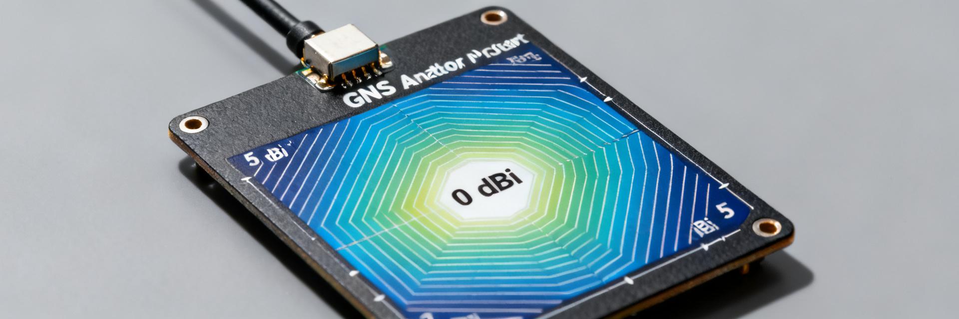
Recent lab surveys of embedded GNSS receivers show that antenna gain and radiation efficiency explain more than 60% of positioning variation in obstructed environments. This article explains what a GNSS antenna’s gain and efficiency mean, why they matter for positioning and power budget, and how engineers should measure, compare, and optimize them.
The goal is practical: give clear definitions, empirical benchmarks by form factor, correct measurement methods, and a compact validation checklist so teams can improve on-device sensitivity, TTFF, and battery life.
Why gain and efficiency matter for GNSS antennas — Background
Definitions: gain vs. efficiency
Point: Antenna gain quantifies directional power concentration (dBi) while efficiency captures losses as a percentage. Evidence: Gain combines directivity with loss factors; efficiency isolates losses from mismatch, dielectric loss, and ground interactions. Explanation: Use dBi for antenna gain and percent (or dB loss) for antenna efficiency; together they determine how much of incident RF energy becomes useful signal at the receiver front end.
System-level impact: positioning, sensitivity, and power budget
Point: Gain and efficiency directly influence SNR, acquisition time, and transmit EIRP for active antennas. Evidence: A 3 dB gain change approximates a halving/doubling of range under free-space assumptions; lower radiation efficiency reduces receive sensitivity and increases needed transmit power. Explanation: In practice, improved antenna gain shortens time-to-first-fix (TTFF) in weak-signal environments, while higher antenna efficiency preserves battery life on duty-cycled or assisted-GNSS receivers.
Empirical benchmarks: typical GNSS antenna gain & efficiency by form factor
Benchmarks by form factor (patch, ceramic, FPC, embedded)
Point: Typical gain and efficiency vary by form factor: patch, ceramic, FPC/printed, and embedded designs. Evidence: Typical ranges—patch: ~2–6 dBi gain with 60–90% efficiency; ceramic: 0–4 dBi with stable 50–85% efficiency; FPC/printed: 0–4 dBi and 40–80% efficiency depending on ground plane. Explanation: Use a compact table in documentation to show form factor × gain range × efficiency; these ranges guide procurement specs and initial simulations.
| Form factor | Typical gain (dBi) | Typical efficiency (%) |
|---|---|---|
| Patch (external) | 2–6 | 60–90 |
| Ceramic (internal) | 0–4 | 50–85 |
| FPC / printed | 0–4 | 40–80 |
| Embedded (on-PCB) | -2–3 | 30–75 |
Environmental & installation effects on measured performance
Point: Ground plane size, enclosure materials, and nearby metal strongly alter measured values. Evidence: Small ground planes can reduce gain by 1–4 dB; metal enclosures may cut efficiency by 10–40% versus plastic housings. Explanation: Document worst-case vs. typical-case numbers (enclosed in plastic vs. metal housing) and always test antennas in final mechanical integration to capture real-world degradation.
How to measure gain and efficiency correctly (measurement & testing)
Gain measurement methods and best practices
Point: Absolute gain measurement requires far-field testing or calibrated comparison; S11 alone is insufficient. Evidence: Use anechoic chamber far-field tests with a reference antenna or properly corrected EIRP measurements; report frequency, polarization, and uncertainty. Explanation: Avoid common pitfalls such as relying on S11 as a proxy for radiation, using inadequate chamber setup, or omitting calibration data. Include gain measurement, test distance, reference specs, and uncertainty in reports.
Measuring radiation/total efficiency and OTA approaches
Point: Multiple methods exist to quantify antenna efficiency; choose one that fits the integration stage. Evidence: Wheeler cap gives a quick radiation-efficiency bound, reverberation chambers yield statistically robust efficiency, and OTA methods capture on-device effects. Explanation: Separate mismatch losses from radiation losses by measuring and de-embedding matching networks; always report percentage efficiency, measurement method, and error bars to ensure comparability.
Design trade-offs & optimization strategies
Improving gain without sacrificing efficiency
Point: It is possible to raise antenna gain while preserving radiation efficiency with targeted changes. Evidence: Tuning ground plane geometry, using optimized low-loss matching networks, and selecting low-loss dielectric materials typically increase gain and maintain high radiation efficiency. Explanation: Balance directional shaping against omnidirectional requirements; prioritize efficiency in low-power receivers and gain when range or link budget is primary. Simulate S-parameters and far-field plots alongside radiation efficiency sweeps.
Layout, ground plane and integration tips
Point: PCB layout and mechanical integration are frequent causes of degraded performance. Evidence: Keepouts, controlled feed-line routing, and avoiding ground voids under a patch unless intended will preserve antenna gain and antenna efficiency. Explanation: Use an integration checklist for enclosures and cables, check connector placement, minimize cable loss, and run quick lab validation after mechanical assembly to catch integration regressions early.
Comparative cases & practical checklist for engineers (case + action)
Comparative benchmark case (compact example)
Point: Small design choices can produce measurable system-level differences. Evidence: In an anonymized comparison, an embedded FPC device vs. an external patch showed a 3 dB gain delta and a 20% higher efficiency for the patch, translating to measurable TTFF and SNR improvements in urban canyon tests. Explanation: Document SNR vs. environment and note which engineering changes (matching, ground plane) produced the gains so teams can prioritize interventions.
Practical specification & validation checklist
Point: A concise procurement and validation spec prevents ambiguity and reduces iterations. Evidence: Include required fields—measured gain at GNSS bands with uncertainty, radiation efficiency method and values, polarization (RHCP) and axial ratio, S11 across band, measurement setup notes, and field verification steps. Explanation: Use pass/fail thresholds, a field sky-test plan, and a troubleshooting flow: low gain → check S11/match → assess enclosure → re-measure isolation and ground-plane effects.
Summary
Optimizing both gain and efficiency of a GNSS antenna is essential for predictable positioning performance, battery life, and system robustness. Key takeaways below synthesize the practical steps engineers should apply before shipping devices; they reference GNSS antenna metrics, gain measurement best practices, and improving GNSS antenna efficiency in final integration.
- Measure with the right methods: report absolute gain (dBi), antenna efficiency (%), frequency, polarization, and uncertainty; include gain measurement details to ensure repeatability.
- Use form-factor benchmarks and test in final integration: compare patch, ceramic, FPC, and embedded ranges and validate in the device enclosure and mounting condition.
- Prioritize fixes based on system needs: prioritize antenna gain for range- and coverage-limited systems, prioritize antenna efficiency for low-power or battery-sensitive designs.
Apply the checklist, run the benchmark table, and validate in-field conditions.
Frequently Asked Questions
How should engineers approach GNSS antenna gain measurement on an embedded product?
Start with an anechoic chamber far-field test using a calibrated reference antenna or corrected EIRP method; report frequency, polarization, test distance, and uncertainty. Complement with OTA or reverberation-chamber efficiency checks after mechanical integration. Avoid using S11 alone as a substitute for gain measurement; de-embed matching networks where possible for clarity.
What’s the difference between radiation efficiency and antenna efficiency for GNSS antenna validation?
Radiation efficiency refers to the fraction of accepted power that is radiated, excluding mismatch losses; antenna efficiency in specs often conflates mismatch and radiation losses. For clear validation, separate mismatch losses (from S11) and radiation losses (from Wheeler cap or chamber methods) and report both numbers with the measurement method.
Which is more important for on-device positioning: higher gain or better efficiency?
It depends on the system: prioritize antenna gain when coverage, range, or antenna diversity is the limiting factor; prioritize antenna efficiency for battery-sensitive receivers or when improving sensitivity without increasing EIRP is desired. Use quick field tests (TTFF, SNR histograms) to decide which lever yields the best system-level improvement.
How do environmental factors like the ground plane affect GNSS antenna performance?
Ground plane size, enclosure materials, and nearby metal strongly alter measured values. Small ground planes can reduce gain by 1–4 dB; metal enclosures may cut efficiency by 10–40% versus plastic housings. Always test antennas in final mechanical integration to capture real-world degradation.


